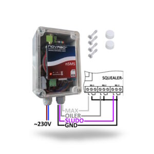
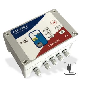
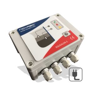
Description
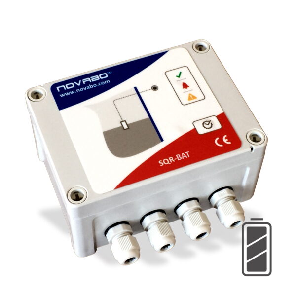
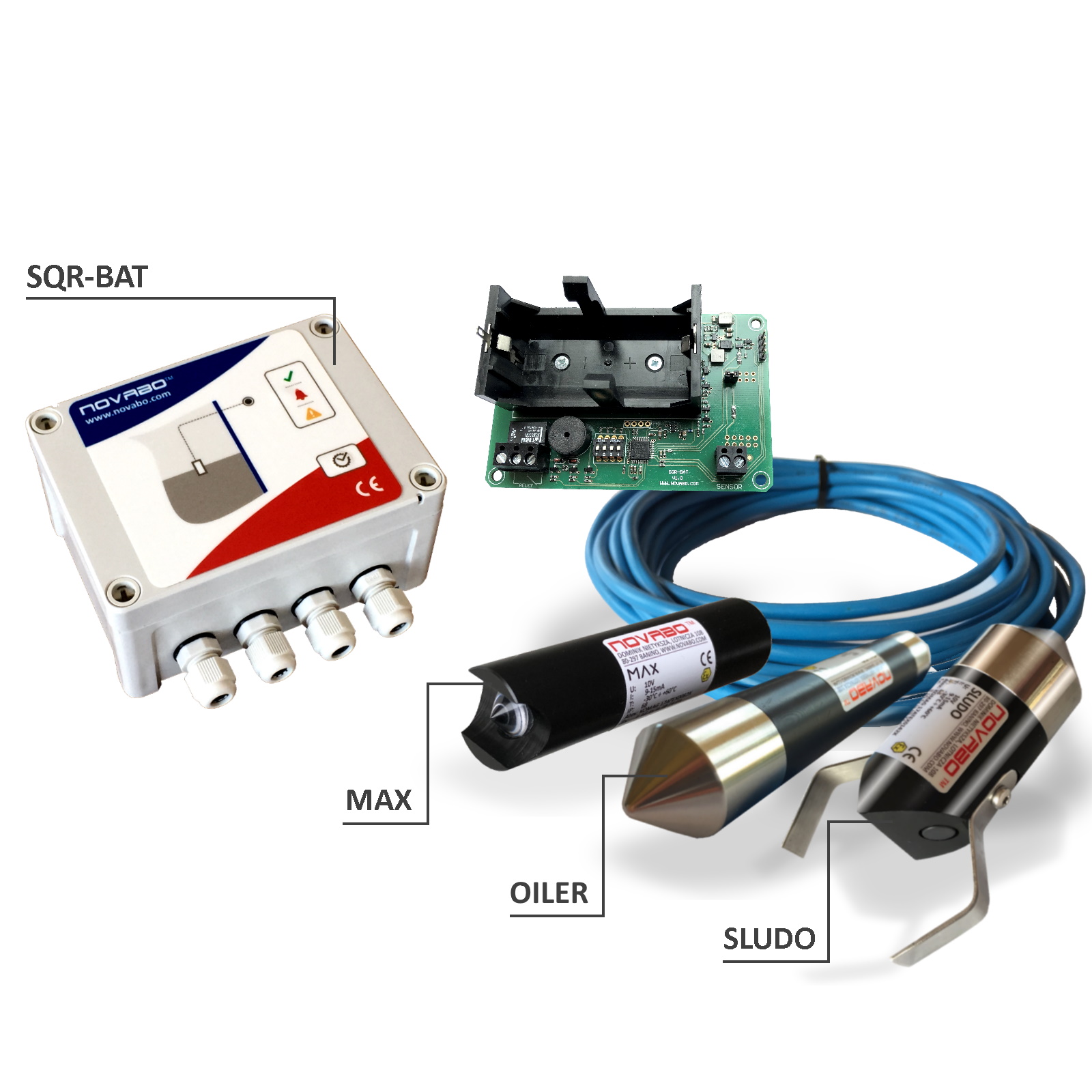
The Squealer-1B controller is a battery-powered device (does not require mains power). Designed as a modern, microprocessor device for continuous monitoring of one of the selected probes (MAX, OILER, SLUDO). The controller works in sleep mode, which is signaled by a green LED flashing every few seconds. Squealer-1B supplies the sensor for 10s every 1 hour and carries out the measurement. If the sensor shows a violation during the measurement, or if there is a short or open circuit, the controller will wake up and start to signal the alarm. The controller can be woken up from sleep by pressing the key for 1 second. If there is no violation of the sensor, after 180s the controller goes to sleep. When the sensor operation is turned off on the DIP-SWITCHes, the controller goes into sleep mode after approx. 15s. If the battery voltage drops below 2.7V, the controller will signal 2 short beeps every 15s. (in sleep and active mode).
The basic hardware parameters of the controller are 1 input, 1 relay output, LEDs indicating normal status, failure status and alarm status, BUZER generating a sound signal informing about an alarm, relay output, activated at the moment of alarm.
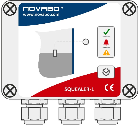
Description of the controller control panel
 ACTIVE MODE
– OK – LED is green – the probe is in a normal state
– ALARM – the LED is blinking red colour to indicate alarm
– TROUBLE – the LED is blinking yellow – signaling a short / open wire
– OFF – The diode is off when the sensor support is off (dipswitch 1 – off)
– Short press of the button during normal state – diode, buzzer and relay operation test is started
– Pressing the button during alarming – clearing the alarm sounding, LED remains on
SLEEP MODE
– OK – the LED flashes green every few seconds.
– A short press of the button wakes up the controller for 180 sec.
Technical data
- 1 input,
- 1 relay output;
- LED diodes indicating normal state, failure and alarm;
- BUZER generating an audible alarm;
- RELAY – relay output NO / NC 0.5A / 125VAC;
- Power supply: battery 3.6V 18Ah (2-3 years battery life);
- ambient temperature: -40 to + 60 ° C;
- mechanical strength: IK 07;
- housing dimensions (without glands) (H x W x D): 96 x 130 x 66 mm;
- cable glands: 2 x M12, cable diameter Ø 4.0-6.0 mm
Installation of probes
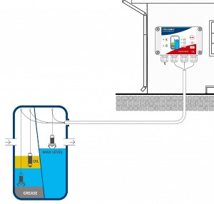
The sensor installation should be carried out as follows:
- Fill the tank with liquid to the maximum level.
- Depending on the tank type, the maximum sludge level, maximum thickness of fat, oil or petroleum substances should be read from the tank manufacturer’s instructions.
- Lower the probe to the pre-set alarm level of the liquid being tested.
- Attach the sensor cable to the mounting eye (for concrete tanks) or through handle (for plastic tanks)
- Then connect the end of the cable to the probe inputs in the controller, maintaining correct polarity +/-.
- In order to extend the cable, use the hermetic NCOUPLER joint.

